R.A.L.P.H - Radar Actuated Lawnmowing Protective Housing
- Role:
- Mechanical Lead
- Date:
- 2025 - 2026
Project Overview
Walk-behind and riding lawnmowers cause thousands of severe injuries annually, with young children representing a disproportionate number of pediatric hospitalizations and limb amputations. My senior year capstone team was tasked with designing and prototyping an active safety system to significantly reduce the likelihood and severity of blade-contact injuries.
As Mechanical Lead, I led the mechanical architecture, mechanism design, analytical modeling, and fabrication of the prototype, while contributing to electrical implementation and system integration. I developed the spring-driven deployment and motor-driven reset mechanisms and used kinematic and structural models to guide their design. The prototype achieved a 46 ± 7 ms guard deployment time and integrated radar-based human detection with an automatically resettable physical barrier.
Problem and Requirements
During the initial requirements-gathering phase, we researched the problem and proposed solutions, evaluated baseline functional requirements, and ideated possible prototypes. Key criteria included:
- Autonomous & Non-Destructive: The system had to actuate without user intervention and maintain mower functionality after triggering (unlike single-use blade-brake systems such as SawStop, which we deemed technically and economically impractical for consumer use).
- Environmentally Robust Sensing: The system needed to differentiate human presence from stationary ambient obstacles or debris, operating reliably across temperature fluctuations, dust, variable weather, and visual obstructions.
- Rapid Physical Interposition: The system must prevent blade contact within the defined detection and deployment timeline without introducing additional hazards.
System Architecture
The final design integrated a mmWave radar sensor with a spring-loaded, deployable physical guard and an automated motor-driven reset mechanism.
- Sensing & Threat Classification: We selected a 60 GHz mmWave radar module which provided range and velocity information that could be used to distinguish human motion from stationary obstacles and other targets. Unlike optical or thermal sensors, radar also works reliably regardless of ambient lighting or thermal variations.
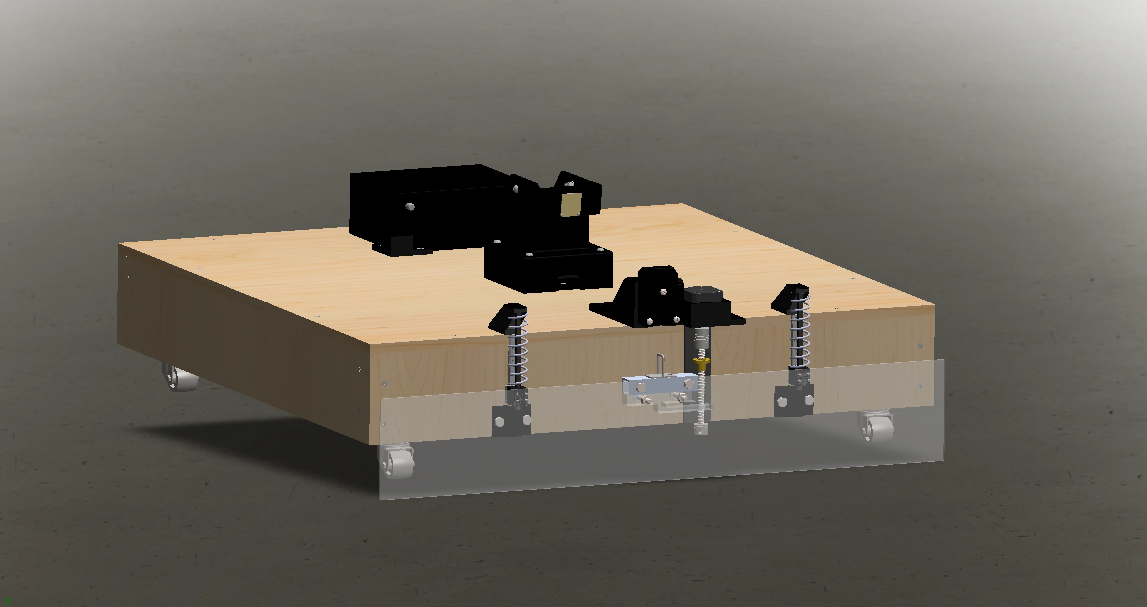
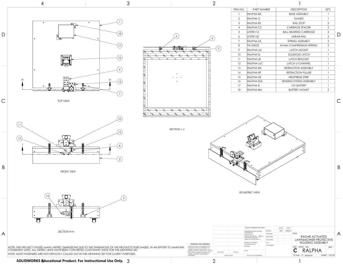
- Deployable Guard Assembly: The guard was fabricated from lightweight aluminum sheet (swapped to transparent polycarbonate for the demonstration prototype to view the internal mechanisms). The guard slides along two low-friction linear guide rails with linear ball-bearing carriages, mounted to a mobile test chassis out of plywood and wheels set to mimic the height of a typical riding mower. Most prototype components were 3D-printed in PETG to reduce fabrication time and cost.
Release and Retraction Systems
My primary responsibility on the team was leading the mechanical design, modeling, and fabrication of the deployment and retraction systems. I also managed the budget and ordering of components.
Deployment Mechanism
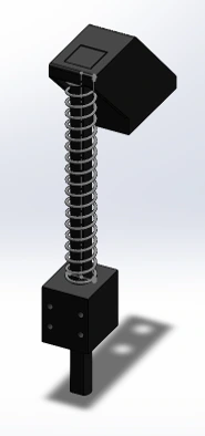
The deployment force is driven by two pre-compressed compression springs. In the primed state, the guard is held against spring compression by a rotary solenoid latching mechanism. Upon receiving a trigger signal, the solenoid fires, releasing the guard to deploy to the ground in 46 ms ± 7 ms (tested across five trials).
Automated Reset Mechanism
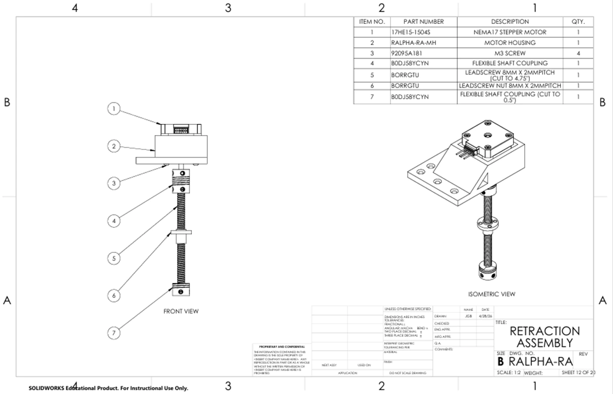
To make the system reusable after actuation, I designed an automated, motor-driven retraction system to reset the guard post-actuation:
- Actuation: Utilized a NEMA 17 stepper motor coupled to a ball screw assembly. A ball screw was chosen over a lead screw to minimize frictional losses and increase efficiency during the reset stroke. The purchased ball screw assembly slipped without load, so I added a friction pad for it to provide the necessary preload.
- Latch Engagement: A custom carriage bracket engages the guard frame and draws it up, compressing the springs, until a limit switch detects full stroke completion and stops the motor.
- Reset: Once the limit switch is triggered and the latch holds the guard, the stepper reverses direction to park the reset bracket below a set of hard stops, preventing it from interfering with subsequent deployments.
Analytical Modeling
I developed several kinematic, timing, and structural models to guide the mechanical design and validate the system prior to building it:
1. Deployment Kinematics & Timing Budget
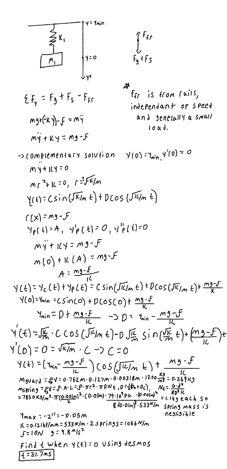
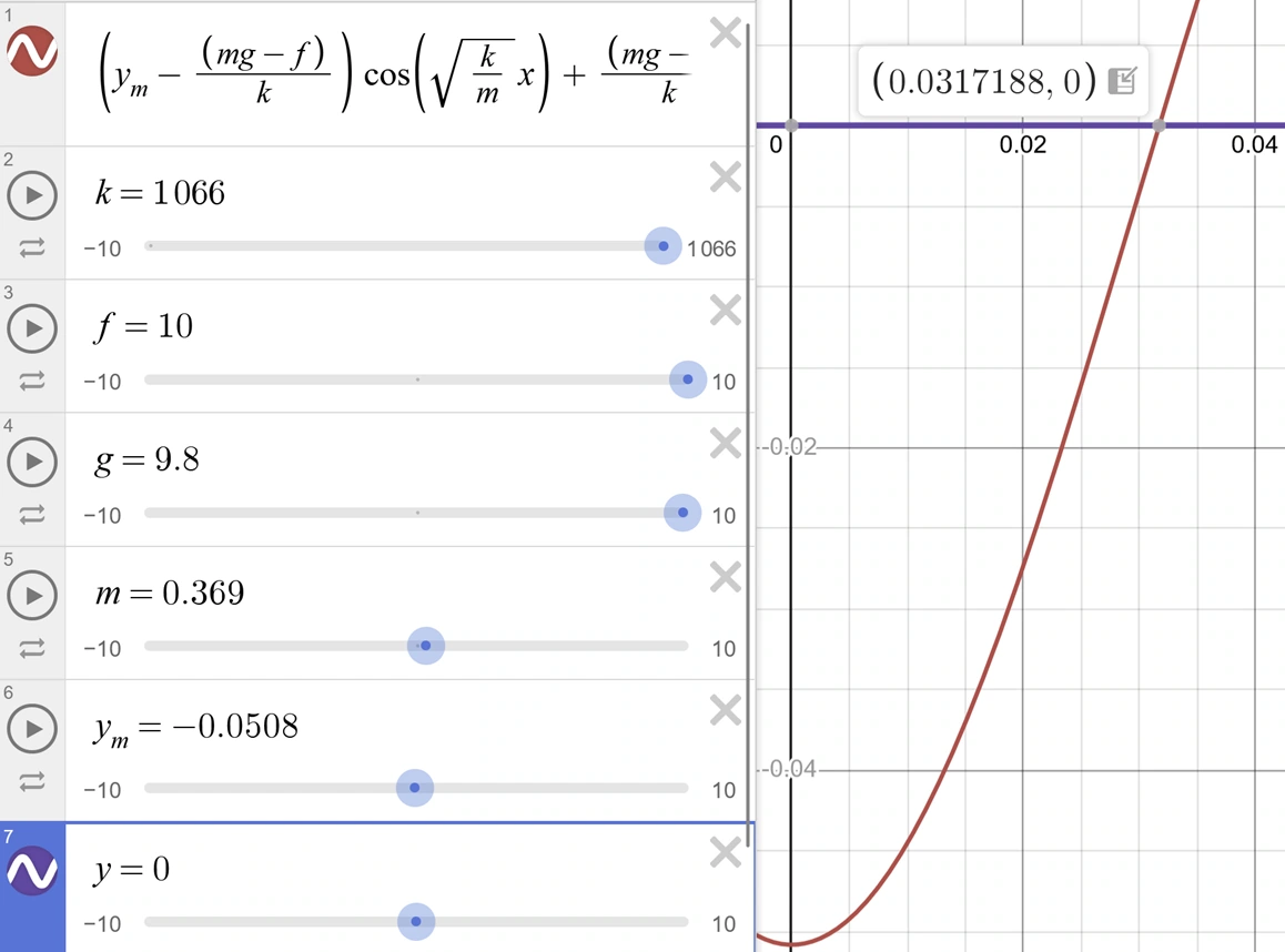
I modeled the deployment subsystem as a single-degree-of-freedom spring-mass oscillator to derive the vertical position over time. I established a worst-case approach velocity of 3.5 m/s based on a child sprinting toward the mower. This velocity, combined with the sensor detection distance, defined the maximum allowable system latency and provided a model to compare different springs to these time requirements. Then, I looked for springs which had the required stiffness, force rating, and 50 mm deployment stroke needed to reach the ground.
2. Guard Structural FEA
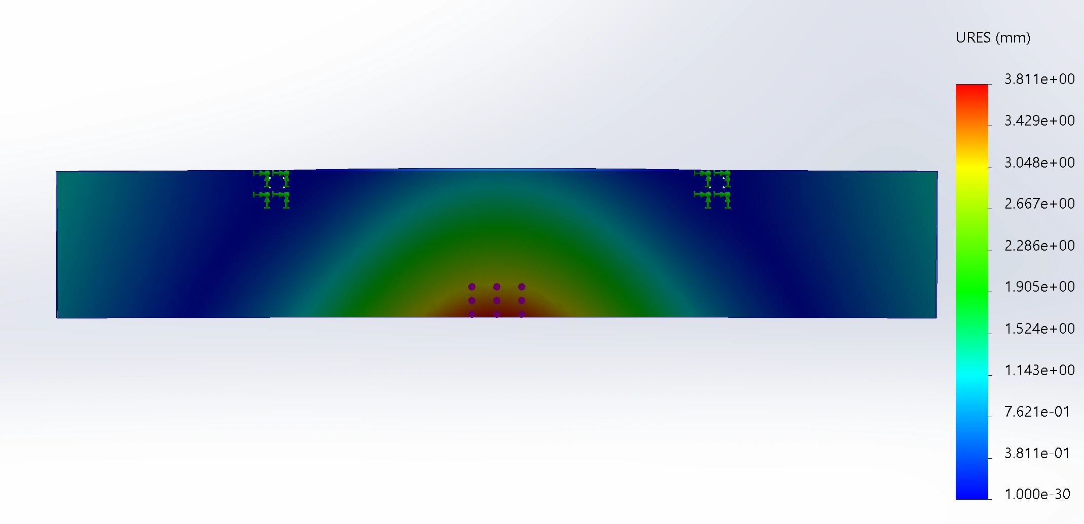
To evaluate whether the deployable barrier could withstand contact from an approaching limb or kick without excessive deformation, I conducted static structural FEA of the aluminum guard. The team estimated a 571 N average kicking force using an impulse-based calculation with an adult foot mass of 0.635 kg, a two-body system mass of 2.5 kg, an assumed kick velocity of 9 m/s, and a 10 ms contact time. Applying a dynamic load factor of 2.0 gave 1,143 N peak design load, which I used for the FEA.
3. Motor Sizing
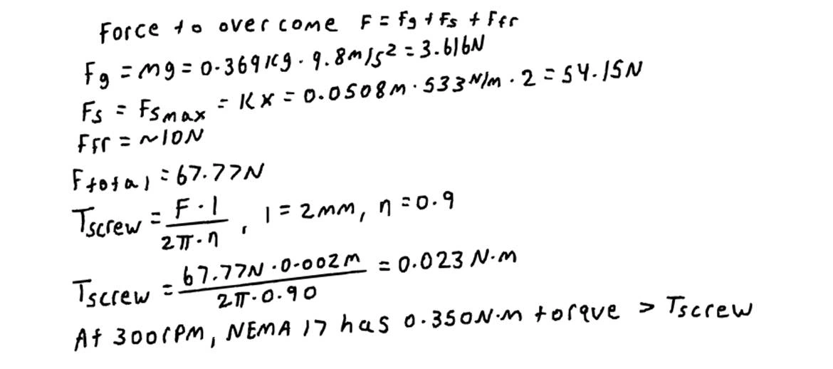
Lastly, I needed to know the required torque to reset the mechanism in a reasonable time. Using the previous force balance, the lead of the ball screw, and a target reset time of under three seconds, I calculated the torque necessary. I then selected a stepper motor capable of providing the required torque at the speed necessary to complete the reset stroke within the target time, accounting for the reduction in available torque at higher speeds.
Electrical Architecture
I proposed the system’s power and control architecture around an ESP32 microcontroller, powered from a 12V lead-acid battery which most riding lawnmowers use.
- Power Bus: A 12V rail for the relay controlling the solenoid actuation splits into a 24V boost converter for the stepper motor driver, and a regulated 5V logic rail for the ESP32, IMU, and mmWave sensor.
- Motor Driver Control: I programmed and implemented the electronics for the stepper motor and solenoid deployment including current limiting and using smooth acceleration at the optimal rpm for maximum torque. I also had to use UART control to disable StealthChop mode and increase step size to achieve this, as the defaults were smooth and quiet but reduced the torque to below what was required.
- Wireless Control: I proposed a Bluetooth interface to test the reset sequence manually and developed test procedures for evaluation.

Results
To test the mower, we set up a detection line based on our requirements and conducted five trials for each of the four test conditions. When either a stationary person or the stationary mower was approached by the other, the system deployed correctly in every trial. The guard also correctly did not deploy when a person walked away from the mower. However, the system triggered in every trial when a person walked perpendicular to the detection zone.
Issues and Future Improvements
Through testing, we identified several issues and areas for future iteration:
- Sensor Processing Latency: While mmWave radar offered excellent target differentiation, firmware processing overhead introduced variable triggering delay which consumed too much of the allowable time budget.
- Rail Alignment & Binding: The dual linear guide setup was sensitive to binding during the retraction phase and occasionally failed to latch.
- Environmental Sealing: The wooden box on wheels demonstrated the concept of the system well, but a commercially viable product would need sealing against grass clippings, moisture, and vibrations, and would require modification to be mounted into the curved deck surface of a real mower.
Overall, the project demonstrated the feasibility of combining spatial sensing with a non-destructive, dynamically deployed barrier for mower safety. It also highlighted the challenges of translating sensing, timing, and mechanical requirements into a reliable physical system under timeline and budget constraints.