Collaborative Robotic Workcell: Gesture-Guided Pneumatic Gripper
- Role:
- Project Lead
- Date:
- Summer 2024
During my time at the Commonwealth Center for Advanced Manufacturing (CCAM), our intern group was tasked with working together to solve a modern manufacturing challenge using collaborative robotics (cobotics). The goal was to use emerging manufacturing technologies while keeping human operators central to the process.
I proposed, and was selected to lead, a concept for an adaptive robotic assistant that uses vision and gesture recognition to locate, hold, and orient heavy parts at convenient angles for operators. By assisting with strenuous steps, the system reduces the need for overhead jacks or rigging, with the goal of reducing ergonomic strain and improving assembly efficiency.
For this project, I designed and fabricated a custom pneumatic gripper and air supply system to securely hold parts, as well as a 3D-printed demonstration assembly for testing. I also managed the project timeline, budget, and status updates to staff.
System Architecture
Our team built the workcell around a Universal Robots UR5 6-axis robot, splitting the scope into four core projects:
- Computer Vision: Integrating a ZED stereo depth camera to detect parts using YOLO and translate their position into the UR5 coordinate system.
- Dynamic Gesture Recognition: A machine learning script using real-time operator hand gestures to control and orient the UR5.
- Control Loop: The central program taking the vision and gesture inputs and translating them into robotic movement based on a set of work instructions and operational procedures for a demonstration assembly
- Demonstration Fixture: A test assembly designed to mimic a real-world assembly task
A Custom Robotic Gripper
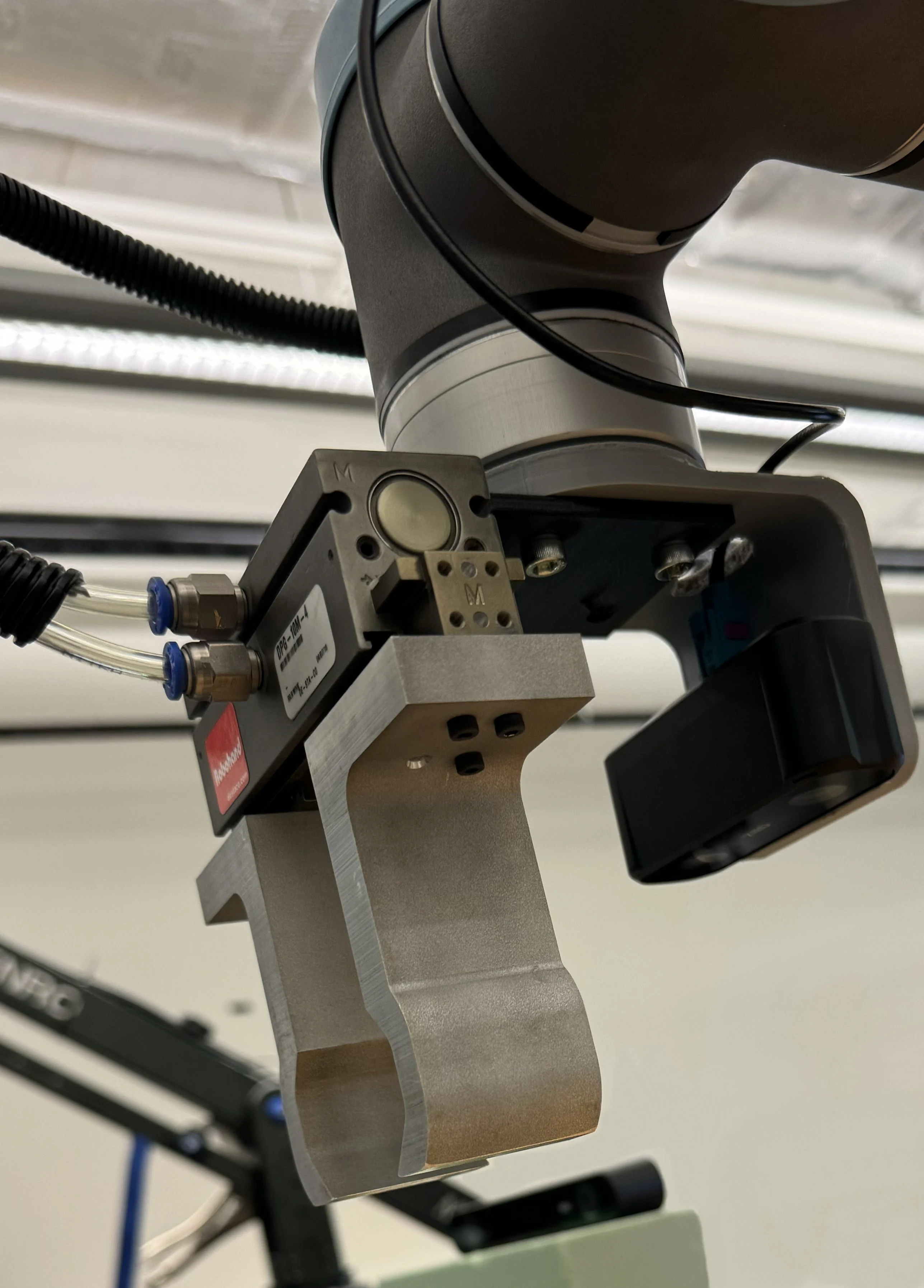
Early in testing, I identified a problem: the robot’s stock electric gripper lacked the clamping force required to hold parts steady while manipulating them. To overcome this, I took on the complete design and fabrication of a custom gripper.
Using Pneumatics
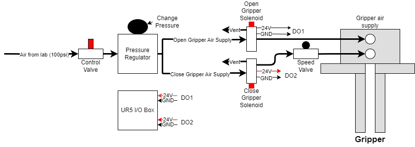
To generate higher clamping force, I looked at ordering a more powerful electrical gripper. However, they were outside our project budget and lacked the flexibility for modification. Instead, I decided to take advantage of the lab’s pressurized air supply and designed a pneumatic actuation system. The pneumatic system provided greater clamping force than the previous gripper while allowing us to customize the gripper geometry.
- Pressure Regulation: I routed an air line through a shutoff valve for safety and a pressure regulator to set the clamping force. The air line then split into two: one for opening and one for closing the gripper. I also added a flow-control valve on the air line that closes the gripper to control the grip speed, preventing pinching of fingers during use.
- Solenoid Control: 24V solenoid valves controlled the opening and closing of the gripper and were connected directly to the UR5 I/O interface, enabling software control through the native programming interface.
Making New Gripper Arms
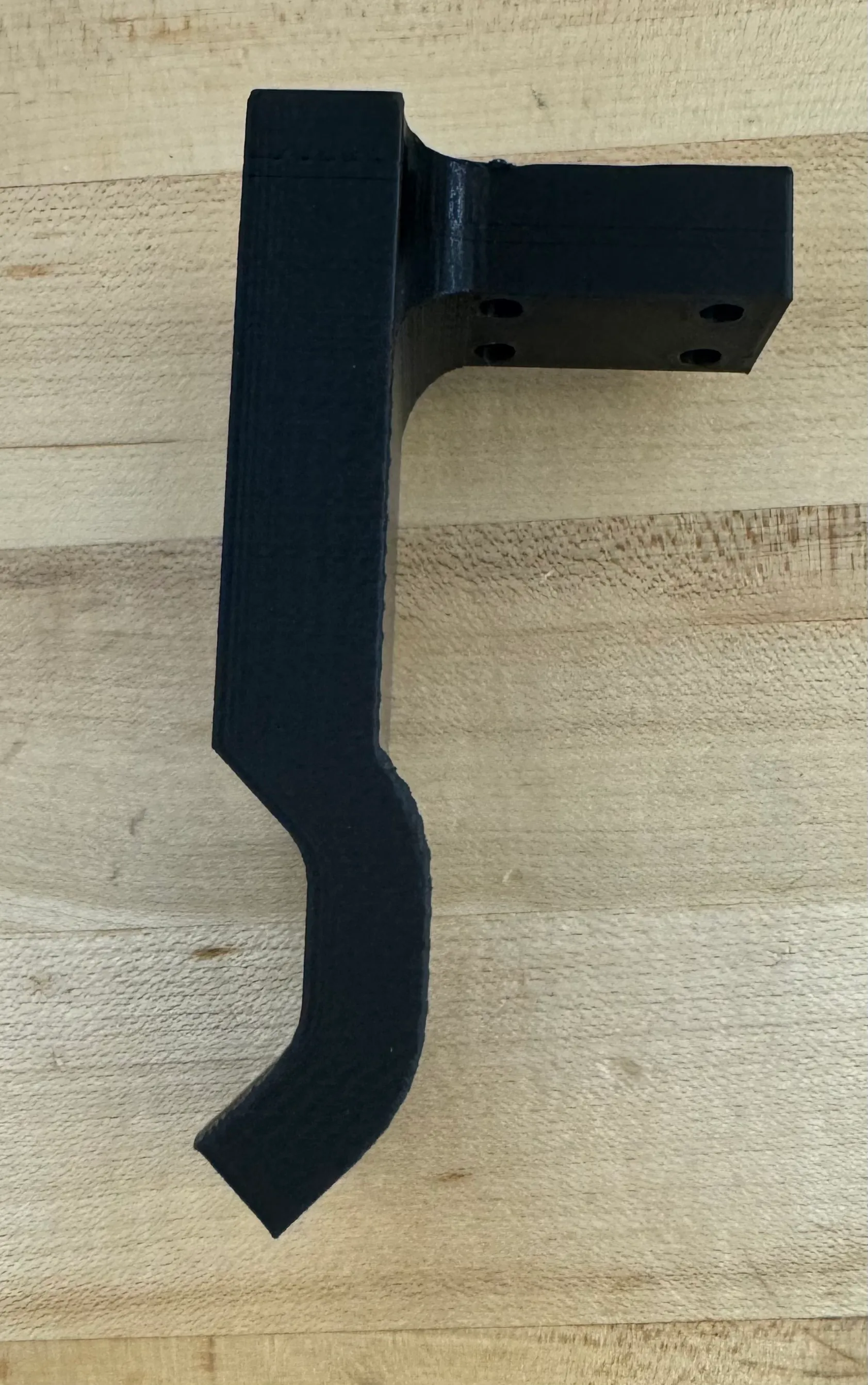
To start, I 3D-printed new gripper arms with the same geometry as the existing ones. However, initial prototypes revealed that using flat jaws even with higher force could not prevent sliding. To solve this, I made several modifications:
- Form-Fitting Profile: I updated the inner jaw profile to a hexagonal shape that mechanically engages the central hub like a wrench.
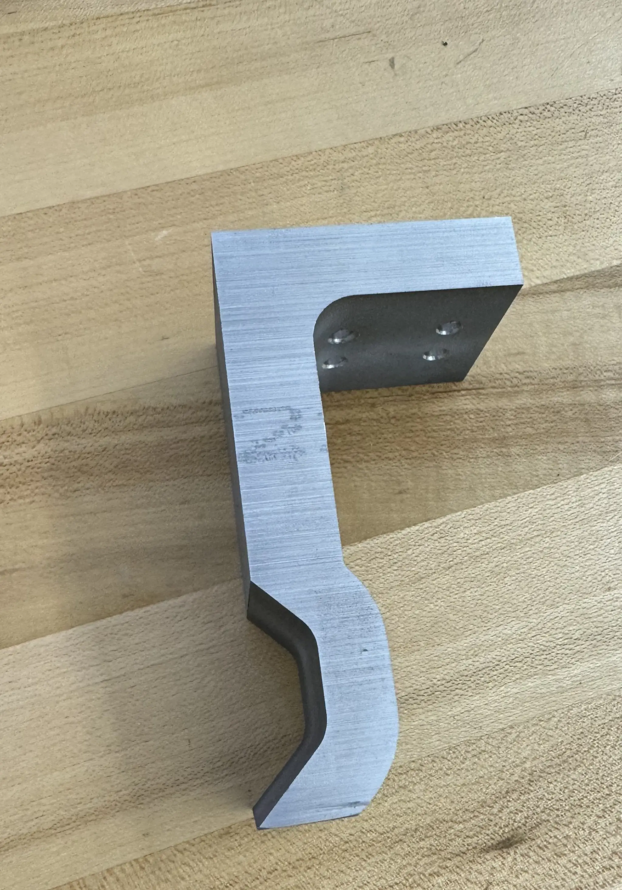
- Wire EDM & Machining: I machined the final jaws from aluminum stock using wire EDM, then drilled mounting holes on a vertical mill to join to the steel baseplate.
- Final Design Iteration: The first aluminum jaws lacked a chamfer at the base and had difficulty gripping the part. I added a lead-in chamfer on the second iteration that allowed the jaws to smoothly guide and align the component.
Helicopter Rotor Demo Assembly
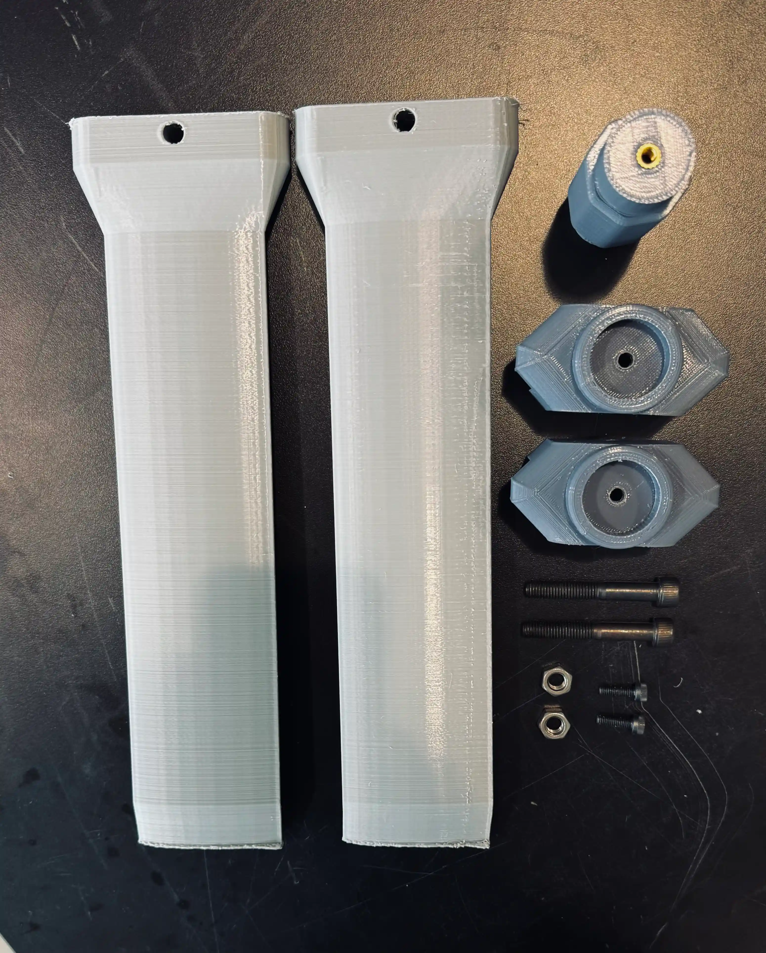
To test the system, I modeled and 3D-printed a multi-part demonstration assembly based on a helicopter main rotor hub and blade pitch assembly (because it’s cool). While this demonstration was plastic for ease of prototyping, it was intended to represent a larger assembly made of steel. Joining these components manually requires an operator to align and screw together heavy parts simultaneously, which would be very challenging for a single individual. Using the UR5 to hold and orient the components was intended to allow a single technician to complete the task with less physical strain.
Vision Integration & Spatial Calibration
I designed and 3D-printed a mount to position the ZED stereo depth camera to see the assembly surface. I wrote a Python script to obtain 3D positions from image pixels using the ZED’s depth data and calibrate them to the robot’s coordinate system using ArUco tags. This allows the detected part locations to be transformed into the robot’s coordinate system so the UR5 can position itself for picking it up.
System Testing
During final testing, each subsystem performed well independently: the ML program successfully classified operator gestures, the computer vision software identified the target components and the ZED camera provided 3D spatial coordinates, and the robotic gripper rigidly held the test parts under load.
However, we ran into integration issues and time constraints toward the end. We had challenges transitioning from one task to the other, and were not able to complete a test run without manual interference.
Main Takeaways
- Integration Takes Time: Our timeline was based around quickly putting the subsystems together, and there was a lack of communication regarding how each part would fit together during individual development. When each person has their own system and assumptions about inputs and outputs, a lot of time is wasted rather than deciding upfront how the main process algorithm should handle data.
- Keeping the Human Element: This project demonstrated that collaborative robotics can augment an operator rather than fully automate the task.