Solar Car: Building a Custom Electric Vehicle (part 1)
- Role:
- Brakes and Steering Lead
- Date:
- 2022 - 2026
Part 1 of 2 in the Solar Car Series
This page covers my first three years on the team—from embedded telemetry and composites to an emergency 5-week sprint to rebuild our steering and braking. For my senior year leading the Brakes & Steering subteam, see Solar Car: Rebuild.
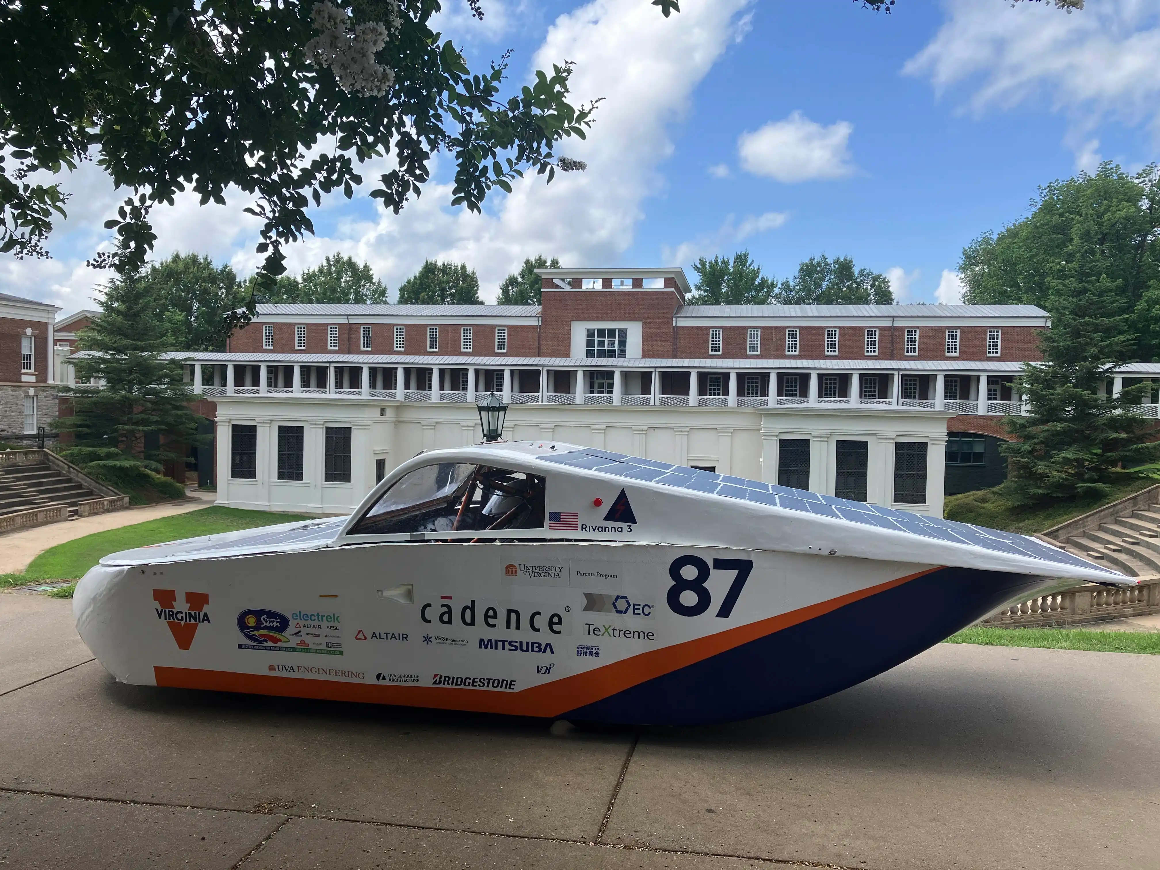
The Solar Car team was one of the defining experiences of my college career. As an entirely student-run organization, we designed, manufactured, and built a solar-powered electric vehicle from scratch to compete in the Formula Sun Grand Prix (FSGP)—an intense multi-day track endurance race.
Over my first three years, I contributed across embedded systems, composite manufacturing, and mechanical design, ultimately taking primary responsibility for rebuilding much of the vehicle’s steering and braking systems during a 5-week push to get the car onto the track. My senior year, I became the Brakes & Steering Subteam Lead and led a broader redesign of the vehicle’s handling and dynamics, which you can read about in Part 2.
If you’re most interested in my hands-on mechanical work, skip ahead to Year 3: A Sprint to the Racetrack.
Year 1: Embedded Systems & Driver Telemetry
My entry to the team focused on embedded electronics and driver interfaces. Our vehicle architecture used custom STM32-based PCBs communicating across an onboard CAN bus, connected to a central Raspberry Pi rendering a live dashboard over a local web server.
Key Contributions:
-
Driver Heads-Up Display (HUD): Modeled UI mockups inspired by modern automotive dashboards, then implemented the layout using React. I then fabricated a custom mounting bracket for the Raspberry Pi screen, and wrote Linux shell automation scripts to start and display the web server.
-
CAN Bus Integration: Wrote Python backend scripts to parse CAN frames, log status messages, and push telemetry to the web display.
-
Hardware Debugging: When our CAN-to-serial converter failed, I worked alongside a teammate to solder serial wires directly into the CAN controller board, writing extra scripts to parse raw hexadecimal data streams into a human-readable backend.
-
Telemetry: Configured an XBee LoRa module to stream live vehicle telemetry to the crew.
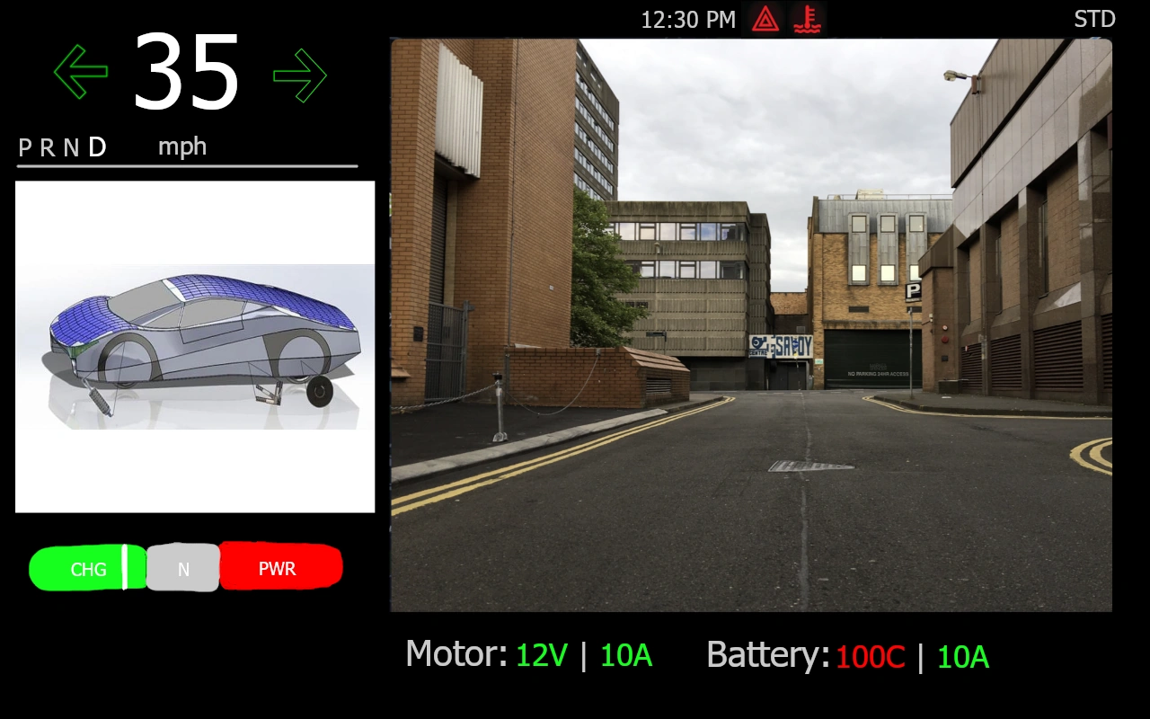
Early mockup for the driver dashboard GUI 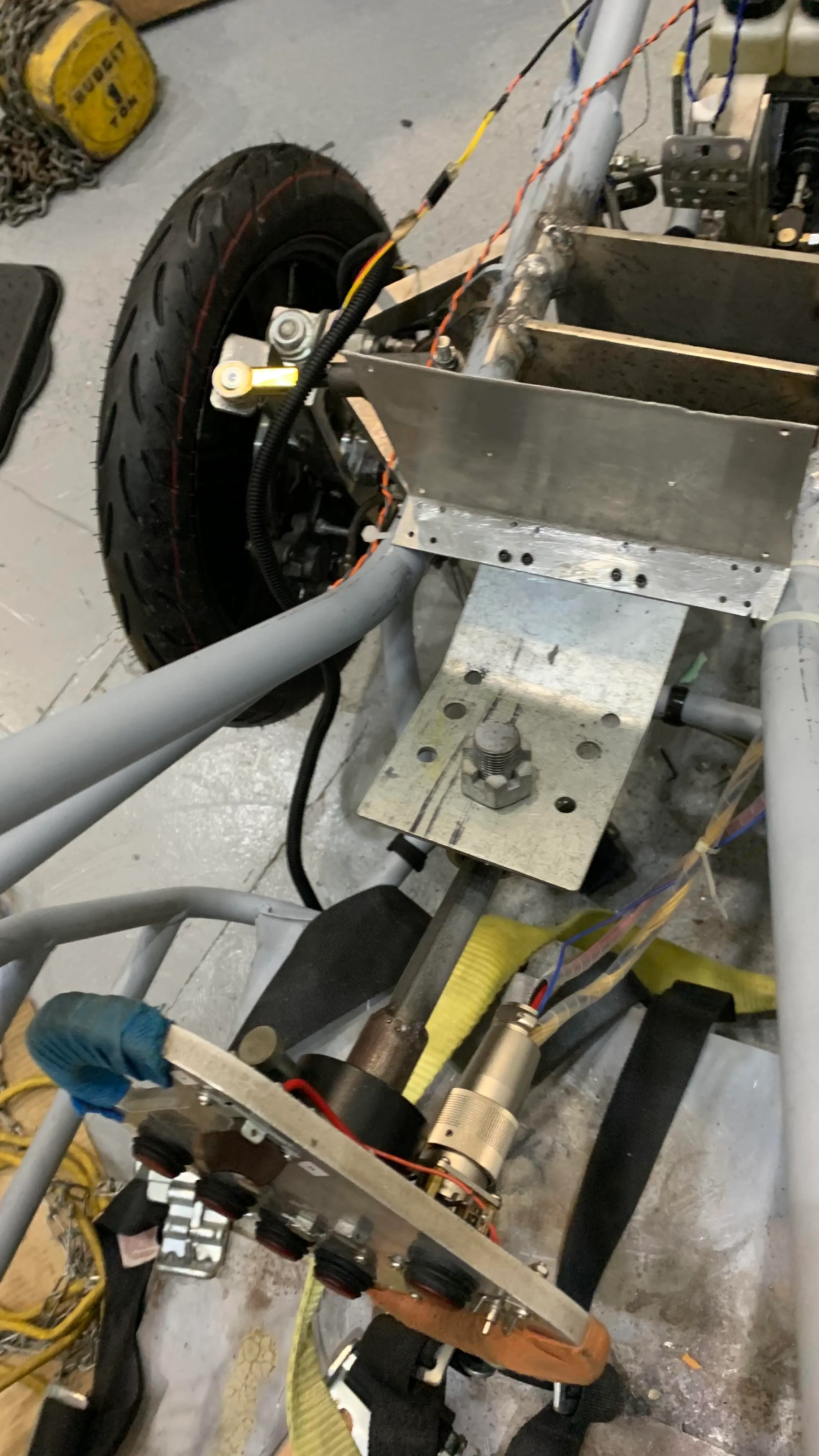
Mount for the driver display
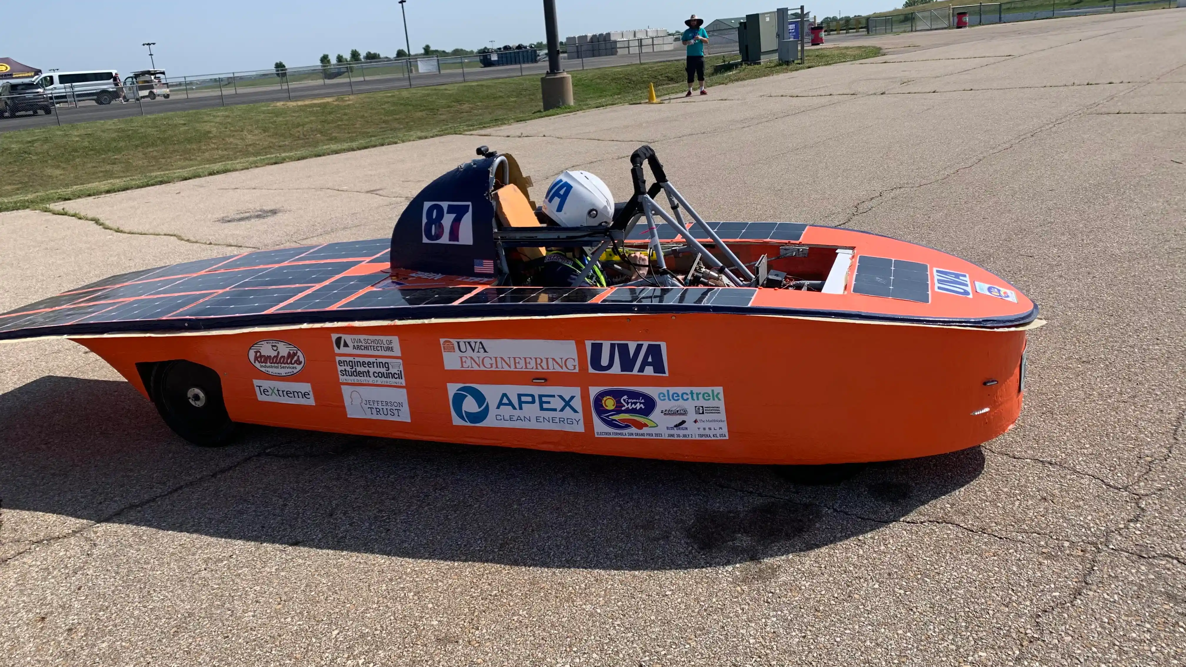
Year 2: Aerobody Composites Development and Testing
During my second year, I transitioned to the aerobody subteam to gain hands-on experience with composite manufacturing techniques.
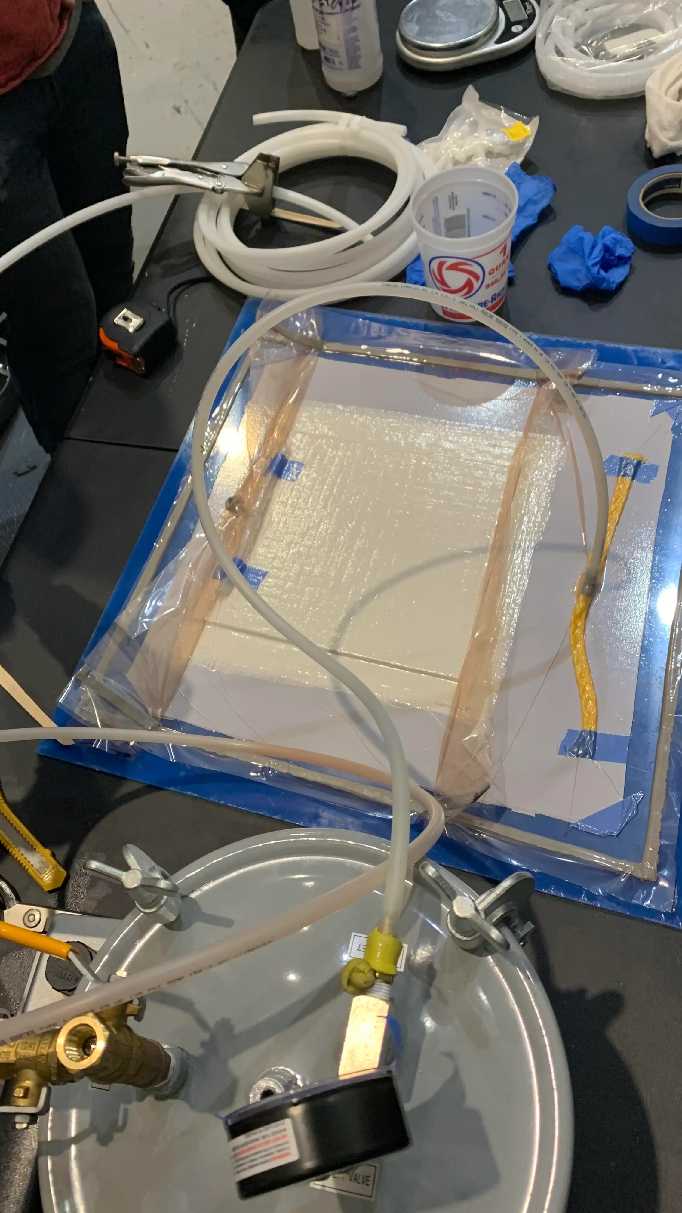
- Wet Layup Optimization: Conducted wet layup trials testing different fibers (fiberglass vs carbon fiber), resin ratios, and vacuum bagging durations.
- Material Characterization: Executed tensile and 3-point bending tests using an Instron universal testing machine to compare yield strength and stiffness across coupon samples.
Year 3: A Sprint to the Racetrack
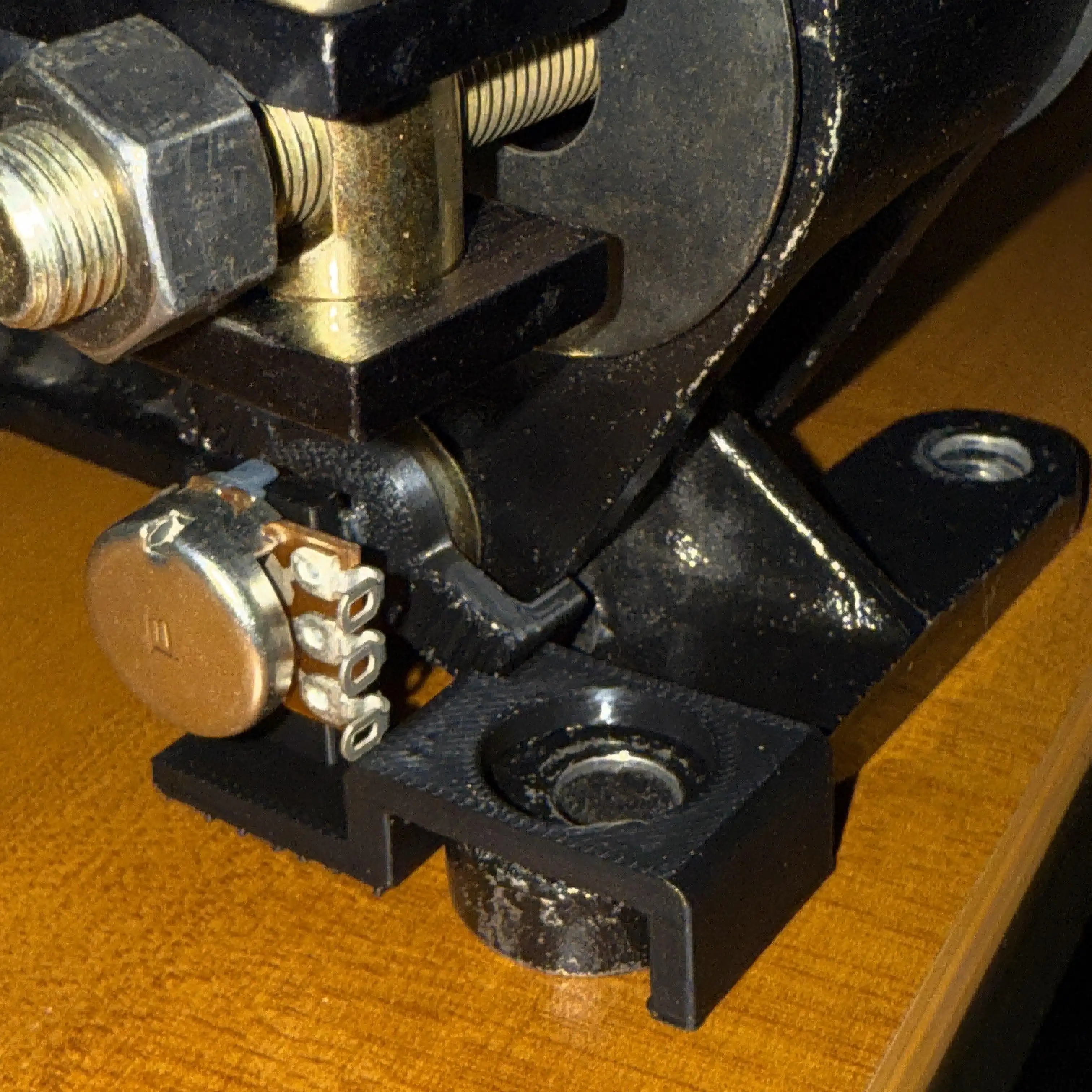
I also worked on replacing our existing brake limit switch with an integrated potentiometer to allow adjustable brake light activation thresholds.
However, by the end of the academic year, timeline slips and design flaws left the vehicle’s steering and braking systems completely non-functional. With the rest of the team leaving campus and the FSGP competition just 5 weeks away, I stayed behind to take primary responsibility for the remaining mechanical work to get us to the race.
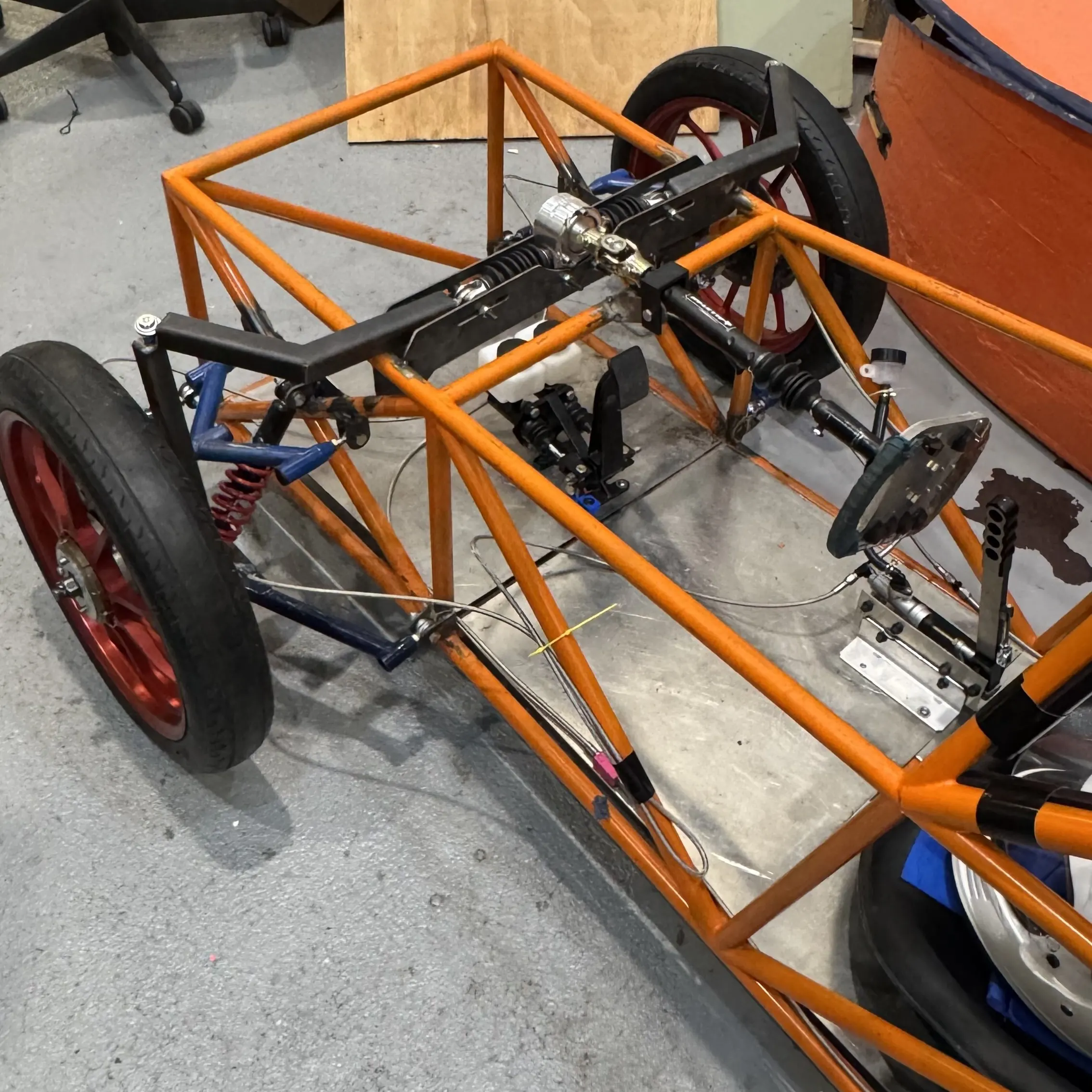
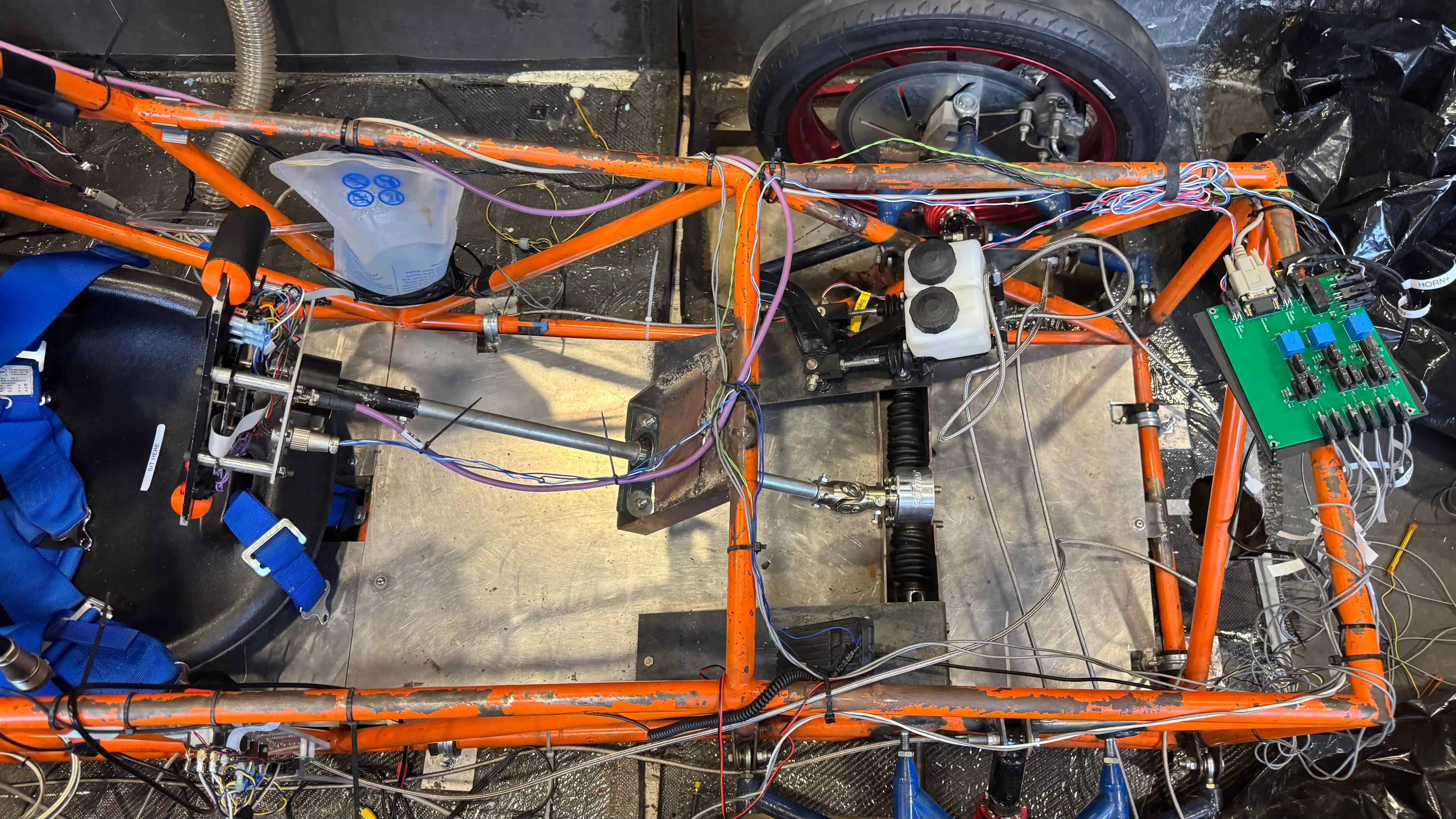
The Steering:
- Steering Shaft Redesign: Replaced the collapsible shaft with a rigid steel shaft. I measured the ideal driver dimensions, used a lathe to make it fit our U-joint, and designed a mount for pillow-block bearings to support the shaft and connect to a chassis cross rib.
- Steering Geometry Optimization: Relocated the poorly positioned steering rack to better align with the control-arm geometry and reduce bump steer. I designed new steering arms to achieve proper Ackermann angles to reduce tire scrub, and calculated the steering arm length to meet turning radius requirements while maintaining a comfortable steering ratio.
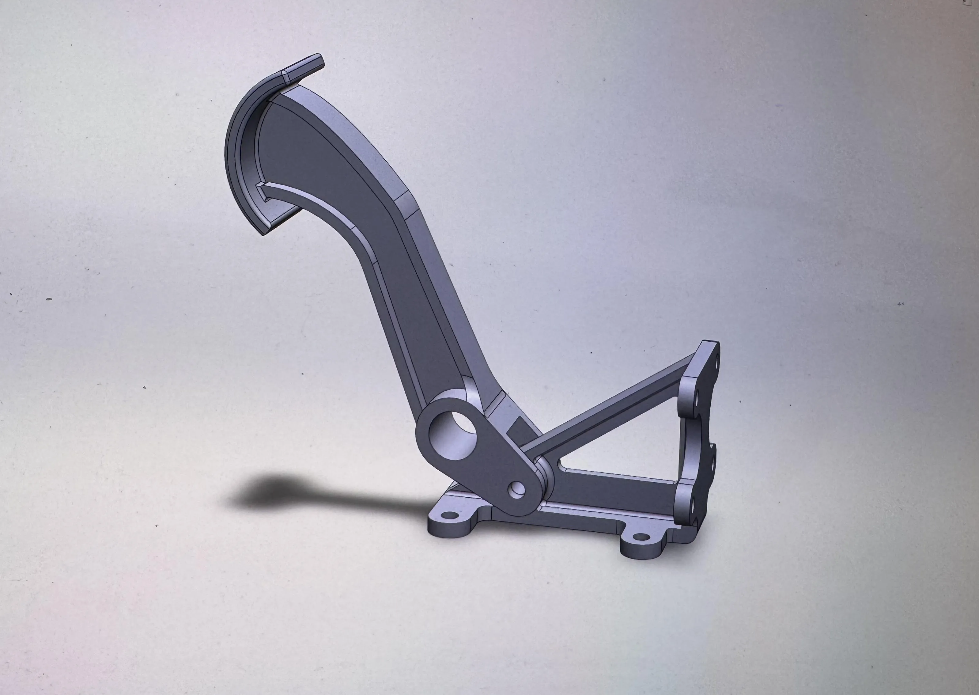
- Pedal Positioning: Separated the brake and accelerator pedals to opposite sides due to spatial constraints. Used the waterjet and sheet metal bender to make ramp mounts, securing them to the baseplate using machined aluminum blocks.
The Brakes:
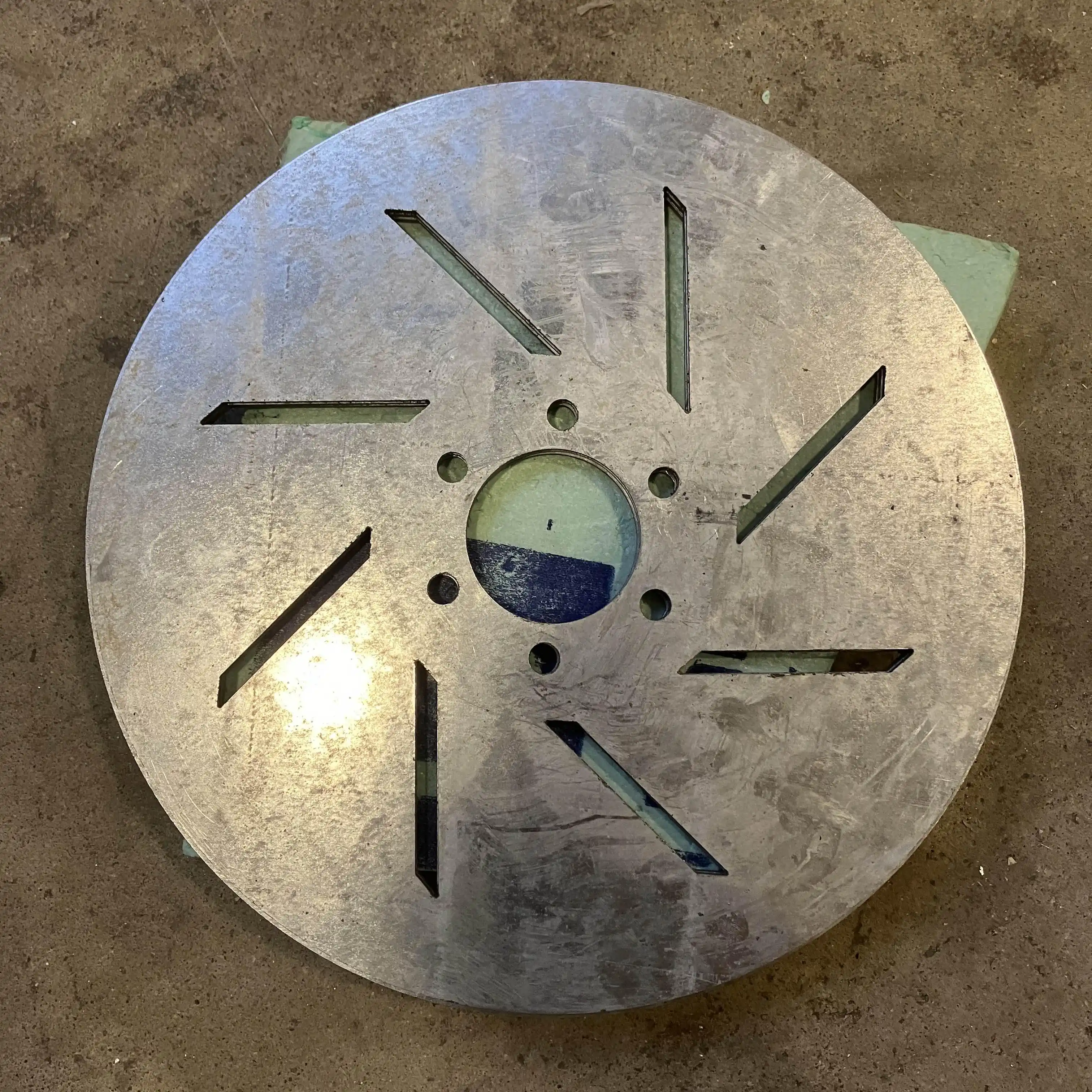
- Brake Rotor Fabrication: We ordered expensive new custom rims and hubs, but they were significantly delayed, arriving just weeks before the race, and lacked any documentation. The hubs ended up incompatible with our existing brake rotors. I designed and waterjet new rotors that fit the hubs, increased the front rotor diameters by 4 in to meet stopping requirements that required the front brakes to lock before the rear brakes, and added slots intended to improve heat dissipation.
- Precision Caliper Spacers: Because the new rotor stock was slightly thicker than the existing ones, the Wilwood PS-1 calipers scraped the edges. I machined 12 spacers on a vertical mill to a ±0.002 in tolerance, eliminating caliper drag.
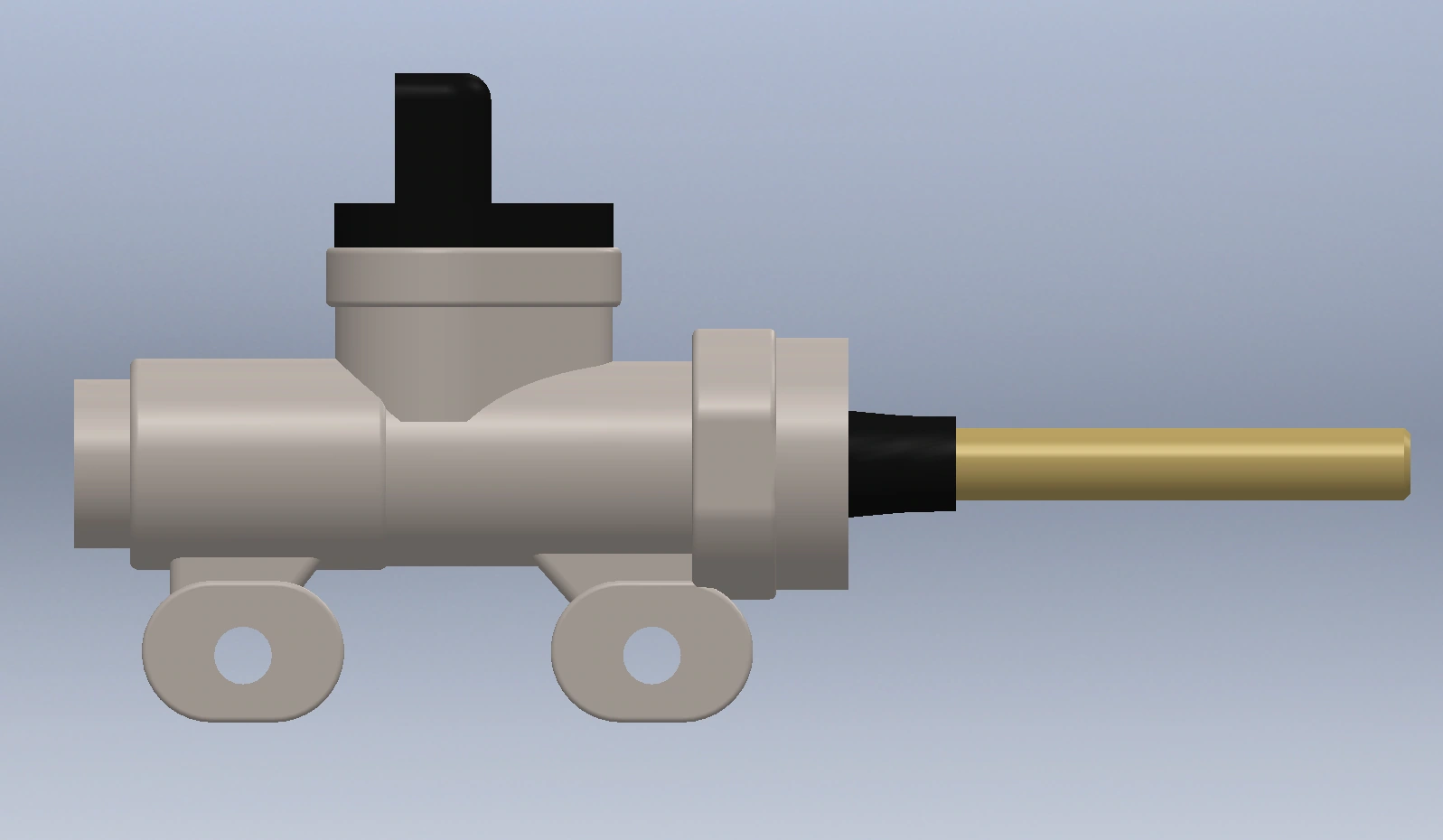
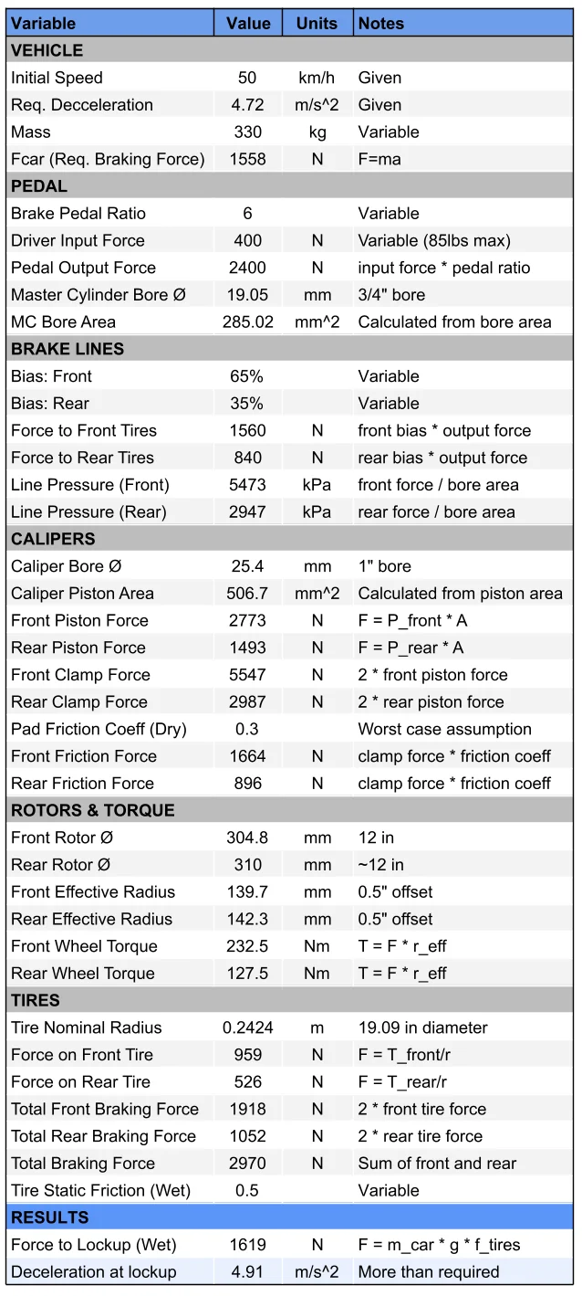
- Brake Lines: Plumbed flexible stainless-steel braided 3AN brake lines to the dual-master-cylinder pedal assembly and adjusted the bias bar. Built an Excel model calculating master cylinder pressures, clamping force, and average deceleration to verify compliance with FSGP regulations.
FSGP Race: The Final Push
Two weeks before departure, our faculty advisor informed us we couldn’t bring the car to competition due to insufficient progress. Instead of deterring us, it motivated a surge of effort. The small remaining crew got the car driving just days before leaving, convincing our advisor to let us head to the track.
What followed were three 16-hour days in the heat trying to pass rigorous technical inspection (called scrutineering).
Troubleshooting & Track Repairs
When mechanical issues surfaced during inspection, we had to adapt quickly on the track:
- Fastener Safety: Replaced standard nuts with Flexloc nuts, added a collar over the lower steering shaft to prevent it from being pulled out, and installed additional safety wire across vibration-prone areas like the hubs.
- Suspension Tuning: Our ground clearance was too low due to soft springs, so I borrowed stiffer rear springs from neighboring teams and swapped them. We also made adjustments to toe, camber, and caster to try to improve stability on the turning tests.
- Hydraulic Leak Mitigation: Diagnosed brake line fluid leaks, removed improperly applied Teflon tape from fittings, and re-bled the system.
- Steering Rigidity: Designed a weld-on plate to stiffen the steering support bracket, and made an aluminum shim out of a Monster can to fix play in the U-joint.
Outcome & Takeaways
The vehicle successfully passed nearly all the dynamic braking and steering tests. However, during the final slalom test, there was instability and oversteer when turning at higher speeds, which we attributed primarily to the vehicle’s estimated 70% rear weight distribution. Despite meeting time targets, scrutineers deemed the handling unsafe for track racing before the start of the race.
In the past, scrutineering could be done throughout the event, meaning we could normally still continue to qualify. Therefore, that evening I calculated the amount of weight shift required and designed a weld-on ballast box to balance the vehicle. However, we soon found out that we were not allowed to continue to attempt qualification due to reservation conflicts with the track, so our race was over.
While very disappointing, the experience proved what our team could achieve under extreme time pressure. It provided invaluable lessons in designing for manufacturability and assembly, in the importance of rigorous testing and conservative timeline planning, and provided a strong motivation to come back stronger next year, where I would be taking a lead role to completely redesign the handling around the issues we faced.